Low Voltage Lighting Controller


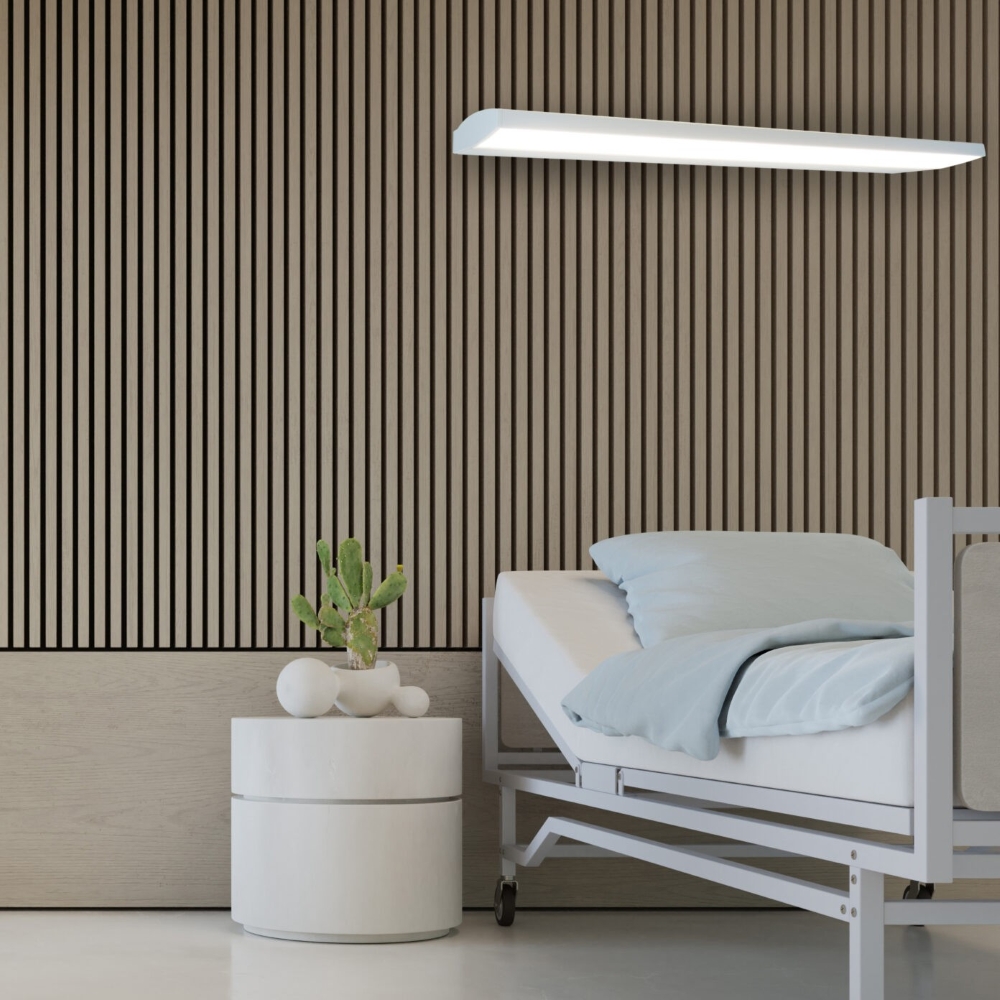
The Low Profile Low Voltage Controller enables users to safely operate the high-voltage lighting found in hospitals and other medical facilities. Appropriate for applications using fluorescent, LED and other lamp types, they are tested and approved with all Nurse Call systems that use a switch. Controls two loads independently, or two loads sequentially and is safe to use near medical equipment that is sensitive to electromagnetic noise.

Designed to mount inside a lighting fixture all connections should be made within the lighting fixture and capped.

The wires on the low voltage side of the units are designated as red, blue and brown. When wiring as a single momentary switch, sequential controller, you must connect the red and blue wires together to one side of the switch. The brown wire is the other side of the switch. Wiring can be connected to a receptacle or directly to a pillow speaker if it is hard wired to the curse call system. When wiring as a two switch combination control, the brown wire is common for the two switches, Blue is S1 and red is S2 (see diagram on page 2)

On the high voltage side the wires are grouped as AC voltage, AC voltage out to the load (light) and input voltage designation.

Features

Input Voltage: 120-277VAC, 60Hz
277VAC, 5A, General and Ballast Use
Output Voltage: 120-277VAC, 60Hz
Switching Circuits
Operation Voltage:
5VDC @ .5 mA
Housing: .032” Galvanized Zinc-Plated steel
Warranty: 3 years

Use

  • The Low Voltage Lighting Controller is designed to provide a quiet, low voltage interface between the patient or staff and the light fixture, drapes, TV, etc.  This provides silent switching as well as safely isolating the user from the line voltage.
  • The VECTOR enclosure is designed to mount into a five-gang [3.5" (90) deep] electrical box or within the light fixture.

Notes

  1. When VECTOR is first energized or when a power interruption of more than one second has occurred, the unit will reset both channels to the off position.
  2. No additional power source should enter the low voltage side of the VECTOR unit. Wiring runs to the SPST switches must be clear.
  3. The use of opto-isolators and solid state switching will appear as a high impedance closed circuit rather than an open circuit when in the "off" condition. The VECTOR should not be used as the primary means of line disconnect in areas where service personnel will be exposed to this current. Before servicing any component being operated by the VECTOR, the power must be turned off on the 'line' side of the VECTOR [such as an upstream circuit breaker] This residual leakage current is not to ground and therefore does not present a hazardous condition.


...
...


Ordering Information

Part Number 028618